Line Follower based on Logic ICs Only
This small project was intended to demonstrate how binary numbers link seemingly distant disciplines. Understanding binary as the foundation of logic connects the dots between the abstract theories of computer science and the tangible world of electronics.
Where The River Meets The Sea
I initially saw ‘1’ and ‘0’ as a means of communication between the machine and the program. It was straightforward: I told the program what to do through whatever language I knew, the program told the machine what to do through binary, and then the program told me what happened using the same language. The conditions were typically perfect, and programs rarely failed due to physical or external factors.
Electronics, on the other hand, seemed more rigid. The logic was described as ‘high’ and ‘low,’ based on physical attributes like the presence of electrical flow. At the time, I perceived this as something fixed: the flow was either present or it wasn’t, making it feel like a one-sided conversation between me and the machine, dictated by the laws of physics.
Getting Started
The days leading up to this project were spent gathering information. Sourcing parts was still difficult despite being located in a larger city in 2015. I probably could have used LEDs to represent the output of the ICs, but I wanted to see the theory in action—executed and validated despite the less-than-perfect conditions.
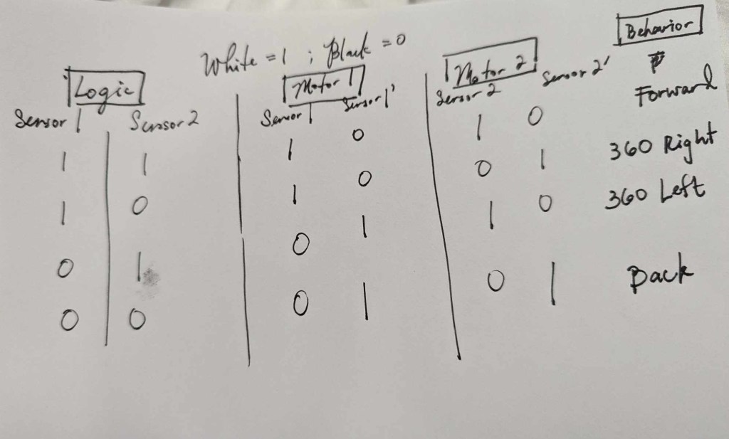
The line follower project had two phases. The first phase utilized ‘NOT’ logic gates (IC7404) to test how accurately the build could track and follow a line. The second phase introduced a more complex track with intersections and dead ends.
Phase 2 was scrapped after I realized I couldn’t cover the cost of printing a new track. I also needed to dedicate more of my time to studying for final exams.
PCB Prototyping
At this time, I also decided to prototype my very first PCB. Without the funds to have it done professionally, I sought ways to do it at home.
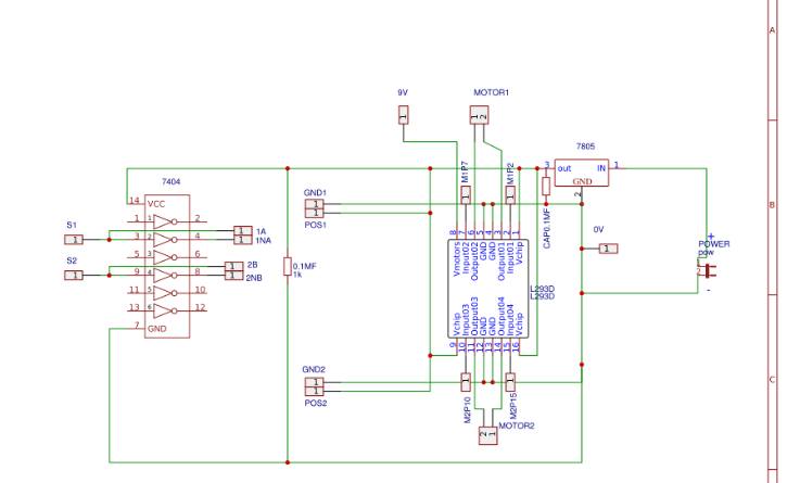
I drew up my schematic using EasyEDA—a website for creating schematics, PCB layouts, and, if you were feeling ambitious, offshore fabrication at $2 for 5 boards. At the time, it was a popular alternative among hobbyists to costly software like Eagle or OrCAD.
Plenty of mistakes were made during this project. At the time, I relied on batteries as a power source, and if I wasn’t careful, it was easy to burn out a costly component. Drawing a schematic, designing a board, and fabricating it each presented its own challenges.
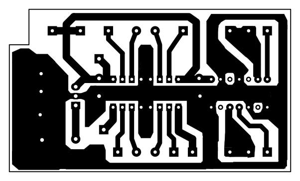
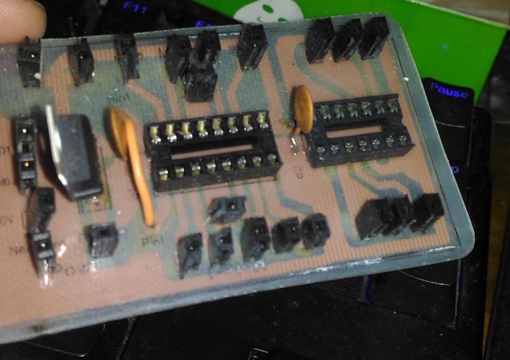
The fabrication process involved using laser print ink to protect the copper during etching. This required heating the print and copper together, removing the residual paper then submerging the assembly in ferric chloride to dissolve the unprotected copper. The board layout had limitations due to the etching process; thick lines and vias were necessary to ensure they wouldn’t dissolve before the board was finished.
Limitations of an Idea
Admitting that I was not well-equipped to tackle such a project by myself was one of the hardest lessons learned.
Knowing that I would have to drill each hole by hand forced me to adapt my design accordingly.
Despite this challenge, I wanted the project to remain modular and reusable for Phase 2. To achieve this, I used headers instead of soldering wires directly to the board. To compensate for the non-standardized spacing between holes, I trimmed the headers (not always perfectly) and soldered each one individually.
Putting the build together was relatively straightforward. It didn’t exactly address the conditions as predicted, nor did it output the desired state on the first try. However, after making some adjustments to the sensors, the build finally functioned as expected.
Final Thoughts: Setting goals and Managing resources
This project strayed quite far from its original intent. While I enjoyed the entire process, proper planning and resource management would have been beneficial. The 2nd Phase didn’t fail because it was impossible to put theory into practice, but because I failed to plan ahead.

There were many hard lessons learned while tackling this project. External factors that I would typically consider negligible in theory—such as heat, brightness, vibrations, and poor connections—proved to be significant in real life and caused failures that left me stumped for days.
