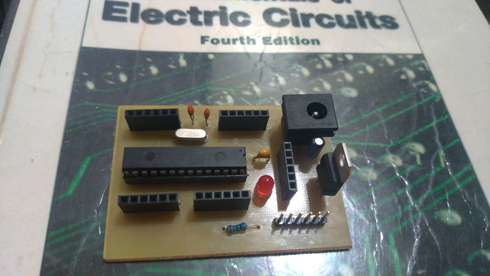
It doesn’t have the solder mask or through-hole plating that a board from a professional manufacturer has, but it’s got heart
Collin Cunningham
PCB Fabrication Attempt 2: Arduino Clone
I love Arduinos. I have always been impressed by how you can condense a multi-component project down with just one board. Removing complexities and costs from hardware is what makes software so invaluable, and the Arduino is great example of that.
DIY or Buy?
Due to the poor postal system in my country, I held off purchasing one for a long time. In 2016, a store in my city finally started selling a few original Unos and Leonardos. However, as a student, $35 was a lot of money. Clones weren’t readily available at the time, and online stores weren’t as accessible as they are now. We had them, but 8 out of 10 times, you would end up getting scammed. So, I settled for the next best thing at the store: the ATmega 328 IC.
It didn’t come in a pretty box like the microcontroller did, but at 1/5th the price with a free 28-pin socket, I couldn’t complain. I was just happy that they even had it in stock.
I built the assembly according to tutorials I found online. It was relatively straightforward, and after flashing it using a UART serial adapter, I had my Arduino Uno on a breadboard. I confirmed its functionality by uploading the ‘Blink’ sketch to the build from the Arduino IDE.
Homeduino
The Homeduino was my attempt at creating a more permanent solution to my microcontroller needs. It was also a great opportunity for me to try making my own PCB at home again. The circuit seemed simple enough, and I already had the knowledge and materials from my last project. So, I set a timeline and began preparing.
EasyEDA
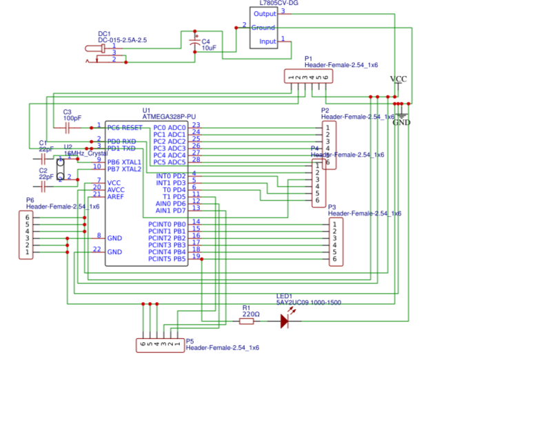
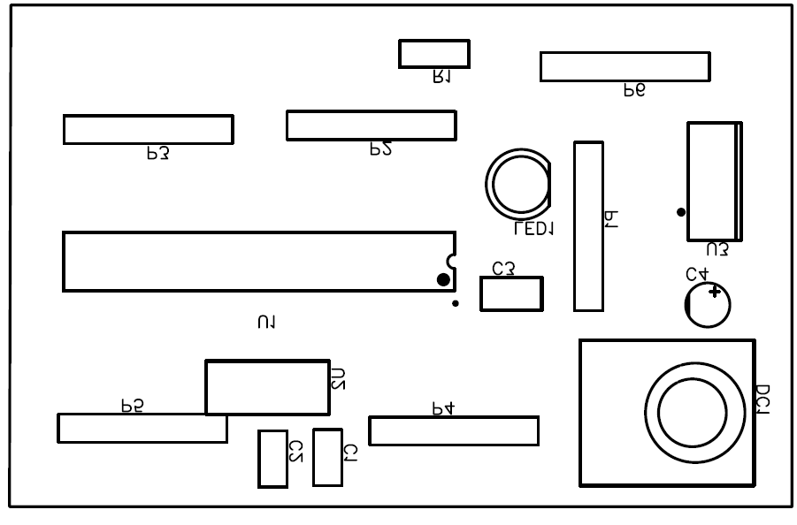
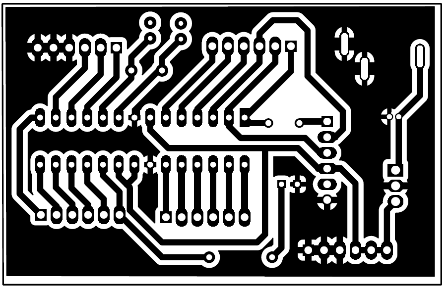
I started by drawing the schematic on EasyEDA. At the time, I didn’t fully understand the importance of component placement and readability, so the schematic ended up a bit more cluttered than what most professionals might be used to. Overlapping components, crisscrossed wire paths, floating ends, and other issues left a lot to be desired. Still, it captured the necessary connections, and in the end, it generated the PCB layout for me to work on.
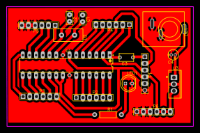
Routing the paths at wider angles was a tip I picked up from a user on EEVblog. I also found that filling the ground plane shortened the etching process. The less copper I had to remove, the shorter the board needed to be submerged in the etching solution, and that reduced the risk of unintentionally losing a trace.
PCB Fabrication
The quality of the image imprinted onto the copper highly depends on the quality of the print itself. Instead of printing it at home, I decided to invest a bit more by having a catalog printing shop print my layout onto photo paper. It was pricier, but I ended up with 25 high-quality copies—far more than I needed. I only hoped I wouldn’t have to use all of them.
By this point, fabricating the PCB wasn’t entirely new to me. I thoroughly cleaned the single-sided fiberglass copper that I was going to use and heated my clothes iron to the highest setting. After spending a minute or two aligning everything, I heat pressed the ink onto the copper and hoped I got it right on the first try.
And I did!
It turned out beautifully, and I couldn’t have been more relieved. So far everything had gone according to plan. I was right on schedule, and if I was careful enough, I could come out with my own homeduino and a whole new sense of validation.
Etching and Drilling
Etching the copper was an even easier task. With a bit of agitation, the ferric chloride easily dissolved the unprotected copper, leaving the print intact. My confidence was at an all-time high, and I knew I had this in the bag. The quality of this project was factors better than the last, and my only regret is that in my enthusiasm to see the final result, I didn’t take any pictures.
The Mistake
A few months before starting this project, I bought a mini benchtop drill press from someone on Facebook Marketplace. I was confident it would solve the alignment issues I experienced with the Line Follower project. While it did address those issues, I also underestimated several factors that came with incorporating this tool into my process.
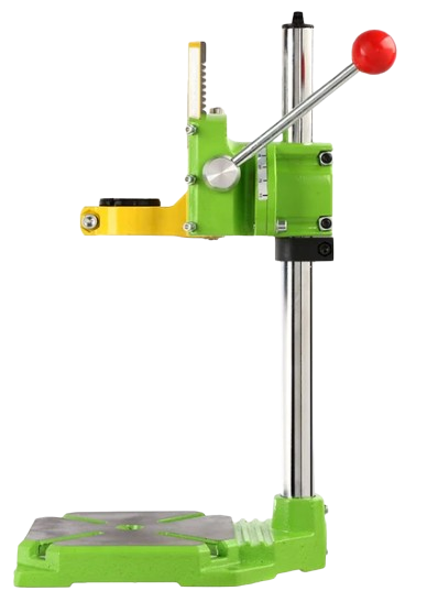
Overconfidence and impatience nearly ruined this project. The moment the HSS bit hit the surface, my PCB slipped from its holder, and the bit cut through one of the traces before snapping. I learned some hard lessons: I completely underestimated the torque of the drill and hadn’t tightened the screws properly. After readjusting the vise and tightening the screws, drilling the holes—though tedious—was successful.
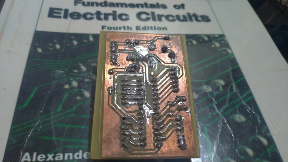
Soldering the components onto the PCB was straightforward, and most importantly, the 28-pin IC socket lined up with the holes as expected. However, while repairing the broken trace, I thought I could simply tin the entire copper layer with solder. I realized before getting too far that my small soldering iron wouldn’t be able to heat up such a large ground plane. So I decided to leave it as is.
Final Thoughts
This was a fun and successful summer project. Extensive planning paid off, and I was able to execute the process without much trouble or additional cost. The Homeduino went on to help me work on small foundational projects before I finally had the funds to purchase my own Arduino.
I could have completed my Arduino project with a perf board, but I wanted to see how much I had improved at PCB fabrication. So, I figured this was a great opportunity to kill two birds with one stone.
